Key takeaways
- An electromagnetic flow meter uses Faraday's law: a conductor moving through a magnetic field creates a voltage.
- It works only on conductive liquids, typically above 5 microsiemens per centimetre.
- There are no moving parts and no pressure loss, so it suits water, wastewater and slurries.
- Liner, electrode material and correct grounding decide long term accuracy.
The electromagnetic flow meter, often called a magmeter, is one of the most widely used meters in water and process industries. It measures flow without any obstruction in the pipe, so it does not wear and does not reduce pressure.
This guide explains the working principle, the main components and the installation rules that keep readings accurate. SWME supplies electromagnetic flowmeters and flow transmitters for municipal, industrial and Oil and Gas applications.
In this guide
The Working Principle
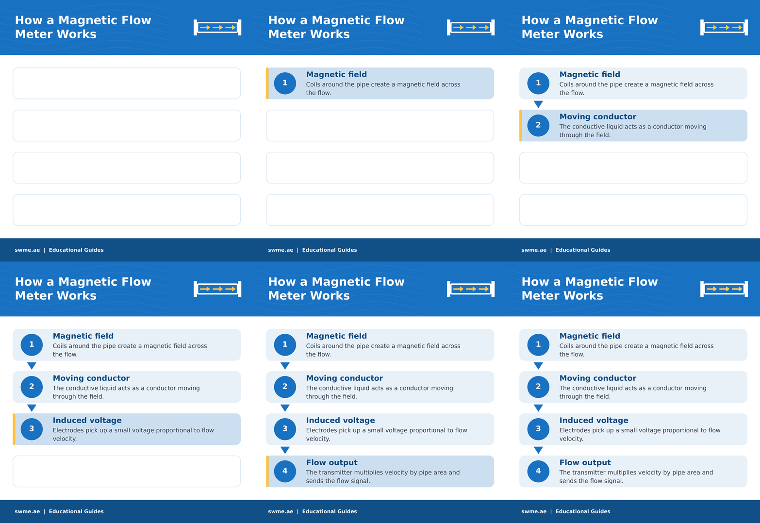
In 1831, Michael Faraday showed that a conductor moving through a magnetic field produces a voltage. In an electromagnetic flow meter, the conductor is the liquid itself. Coils on the outside of the meter tube create a magnetic field across the pipe. As the liquid flows, a voltage appears between two electrodes mounted on opposite sides of the tube.
The voltage is directly proportional to the average flow velocity. The transmitter multiplies this velocity by the pipe cross section to give volume flow. For example, a velocity of 2 metres per second in a 100 mm pipe gives about 56.5 cubic metres per hour.
Key points about the signal
Did you know?
An electromagnetic flow meter does not care about viscosity, density or temperature, as long as the liquid is conductive. Thick slurries and clean water give the same accuracy. However, pure hydrocarbons and demineralised water are not conductive enough to measure.
Main Components
| Component | Function | Typical options |
|---|---|---|
| Meter tube | Carries the flow and supports the coils | Stainless steel, non magnetic |
| Liner | Insulates the liquid from the metal tube | PTFE, PFA, hard rubber, polyurethane |
| Electrodes | Pick up the induced voltage | 316L, Hastelloy C, titanium, platinum |
| Coils | Create the magnetic field | Pulsed DC excitation |
| Transmitter | Converts voltage to flow and output | 4 to 20 mA, pulse, HART, Modbus |
Liner and Electrode Selection
Liner choice
- Hard rubber for potable water and wastewater.
- Polyurethane for abrasive slurries and mining.
- PTFE or PFA for chemicals and high temperatures.
- Check vacuum rating; some liners collapse under vacuum.
Electrode choice
- 316L stainless steel for water and mild media.
- Hastelloy C for chlorides and seawater.
- Titanium or tantalum for strong acids.
- Scraper or flush electrodes for coating media.
Sizing an Electromagnetic Flow Meter
Size the meter for velocity, not just for the pipe. The ideal velocity range is about 1 to 5 metres per second. Below 0.5 metres per second, accuracy falls; above 10 metres per second, abrasive media wear the liner quickly. You can check velocity with the pipe flow velocity calculator.
Where velocity is too low, a smaller meter with reducers raises the velocity and improves accuracy. In addition, a smaller electromagnetic flow meter is often less expensive.
To scale the output signal in your control system, use the 4 to 20 mA scaling calculator or the PLC analog scaling calculator. For PLC input cards, see this guide to PLC hardware selection.
Installation and Grounding
- Keep the pipe full. Install in a rising line or a low point; partly full pipes give large errors.
- Straight runs. Provide at least 5 diameters upstream and 2 downstream of the meter.
- Electrode orientation. Keep the electrode axis horizontal so air bubbles do not cover an electrode.
- Grounding. Bond the meter to the liquid with grounding rings or electrodes, especially in plastic or lined pipes.
- Avoid strong fields. Keep the meter away from large motors and variable speed drives.
- Cable routing. Use separate cables for signal and power on remote transmitter versions.
Grounding deserves special attention. The electromagnetic flow meter measures millivolts, and stray currents in the pipe can be larger than the flow signal. For background on sensors and signals, see the flow measurement articles on instrumentationblog.in. For other technologies, read types of flow meters explained.
Common Mistakes to Avoid
If readings already look wrong, our guide on flow meter incorrect readings lists the usual causes.
Frequently Asked Questions
What is the minimum conductivity for a magnetic flow meter?
Most meters need at least 5 microsiemens per centimetre. Special designs can measure down to about 0.05 microsiemens per centimetre.
Does an electromagnetic flow meter need straight pipe?
Yes, but less than most meters. Around 5 diameters upstream and 2 downstream is a common requirement.
Can it measure flow in both directions?
Yes. Most transmitters measure forward and reverse flow and can totalise each direction separately.
