Key takeaways
- Guided wave radar sends low power pulses down a probe and times the echo from the product surface.
- The echo strength depends on the dielectric constant: water (about 80) reflects strongly, oil (about 2) much less.
- A second echo from a lower, higher dielectric liquid lets one transmitter measure both level and interface.
- Probe choice, nozzle size and clearance from metal decide whether the reading is reliable.
Many tanks, separators and bypass chambers need a level reading that does not drift with density, pressure or temperature. Guided wave radar, often shortened to GWR, meets that need with a probe that hangs into the liquid and a pulse that is timed electronically.
This guide explains how it works, how to pick a probe and how to avoid the usual installation problems. SWME supplies level transmitters and level gauges for process plants across the GCC.
In this guide
How Guided Wave Radar Works
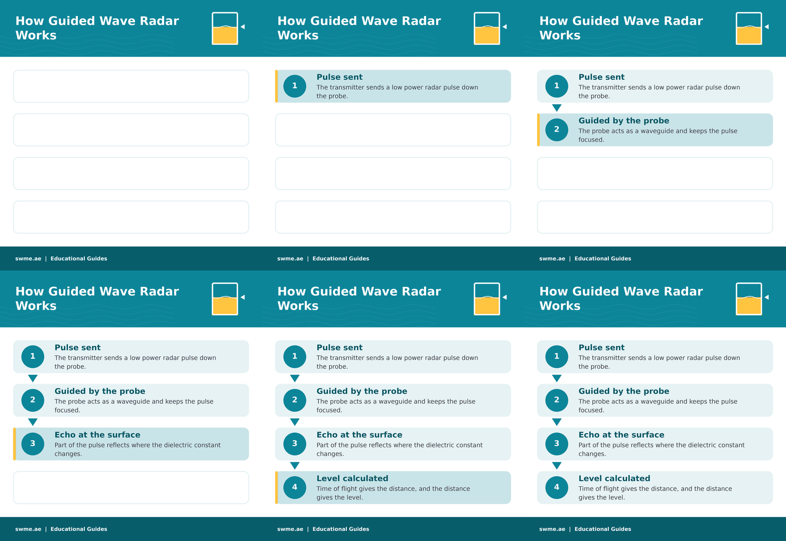
According to Emerson, GWR uses time domain reflectometry. The transmitter sends radar pulses down a probe that acts as a waveguide. When a pulse meets the product surface, part of it reflects back. The transmitter measures the time between sending the pulse and receiving the echo, converts it to a distance and subtracts that distance from the reference height to give level.
At a glance
Dielectric Constant and Interface
The size of the echo depends on the dielectric constant, or relative permittivity, of the product. Emerson gives water at about 80 and oil at about 2, and states that its high sensitivity transmitters measure media down to a dielectric constant of 1.2. Check the value for your own product with the supplier before you order.
For interface, the first echo comes from the top liquid and the remaining energy reflects again at the lower liquid. Chemical Processing adds three conditions: the lower dielectric fluid must be on top, its dielectric value must be known, and the two liquids should differ by at least about 10. For example, a hydrocarbon layer of about 2 over a water based layer above 40 works well, while emulsions are hard to measure.
Probe Types
| Probe | Best for | Watch out for |
|---|---|---|
| Coaxial | Clean liquids, short to medium ranges, bypass chambers; high signal strength | Clogging and buildup in dirty service |
| Rigid single lead | Shorter chambers, low dielectric products and interface | Must not touch the chamber wall |
| Flexible single lead | Tall tanks and limited headroom | Needs a weight and must stay clear of the wall |
| Segmented single lead | Tall chambers and pipes up to 10 m with limited headroom | Assembly length and centring |
| Twin lead | General liquids | Clogging and buildup in sticky service |
Probe uses come from Emerson, and the buildup notes from Chemical Processing, which recommends single lead probes for dirty, sticky or coating liquids. For level in a chamber, our guide to how a magnetic level gauge works shows how a GWR transmitter often shares a chamber with a float indicator.
Did you know?
Steam is one of the few vapours that affects GWR. Chemical Processing notes that above roughly 30 to 35 bar steam pressure, guided wave radar needs dynamic vapour compensation to stay accurate in boiler drums and feedwater heaters.
Installation Checklist
- Nozzle size. Chemical Processing advises nozzles at least 2 inches in diameter and no more than 6 inches high.
- Clear the probe. Keep the probe away from the wall, pipes, baffles and agitators. Only a coaxial probe may touch metal.
- Chamber size. Use 75 mm or 100 mm chambers; smaller chambers raise the risk of buildup and wall contact.
- Keep flow off the probe. Do not let a fill stream fall onto the probe or into the measuring path.
- Heat viscous service. Insulate and heat trace chambers on viscous products, or choose a non contacting radar.
- Set the medium. Enter the correct dielectric and thresholds, since oil and water need different settings.
Strengths and Limits
Strengths
- Level and interface from one device
- Works on liquids, sludges, slurries and some solids
- No moving parts and little maintenance
- Unaffected by density changes
Limits
- Probe is in contact with the product
- Not suited near agitators, pumps or hopper outlets
- Very viscous or heavily coating products
- Metal contact degrades the signal
If the probe cannot go into the vessel, read radar vs ultrasonic level measurement. For a pressure based option, see DP level measurement in closed tanks.
Common Mistakes to Avoid
For field faults, Instrumentation Blog has a GWR troubleshooting guide, and our post on level transmitter calibration mistakes covers setup errors. To turn level into volume, try the vertical tank volume calculator.
Frequently Asked Questions
What is guided wave radar?
A level transmitter that sends radar pulses down a probe and times the echo from the product surface to calculate level.
Can guided wave radar measure interface?
Yes, when a lower dielectric liquid sits on top of a higher dielectric liquid and the two differ by at least about 10.
Which probe suits sticky liquids?
A single lead probe, because coaxial and twin probes are more prone to clogging and buildup.
