Key takeaways
- A pressure transmitter measures process pressure and converts it into a standard electrical signal for your control system.
- Most industrial models send a 4 to 20 mA signal, often with HART digital communication on top.
- Correct range, wetted materials, process connection and hazardous area approval decide long term reliability.
- Good installation practice matters as much as the instrument itself.
A pressure transmitter is a field instrument that measures the pressure of a liquid, gas or steam and converts it into a standard electrical signal. The control system, usually a PLC or DCS, reads this signal to monitor the process, run control loops and trigger alarms. In Oil and Gas, Petrochemical, Water and Utilities plants, it is one of the most common instruments on site, and SWME supplies pressure transmitters from leading principals for all of these industries.
This guide explains how a pressure transmitter works, which sensor technologies are used, how output signals differ and how to select and install the right model for your application.
In this guide
What a Pressure Transmitter Does
A pressure gauge shows pressure to an operator standing next to it. A pressure transmitter sends the same information to a control room, many metres or even kilometres away. This allows the plant to record trends, close control loops and shut down equipment safely when limits are exceeded.
For example, a transmitter on a pump discharge line can tell the control system that pressure is rising because a downstream valve has closed. The system can then reduce pump speed or stop the pump before the line is overpressured. In addition, the same signal can be logged for maintenance teams to study later.
At a glance
How a Pressure Transmitter Works
Every pressure transmitter follows the same basic chain from process to signal. Understanding this chain helps you diagnose problems in the field.
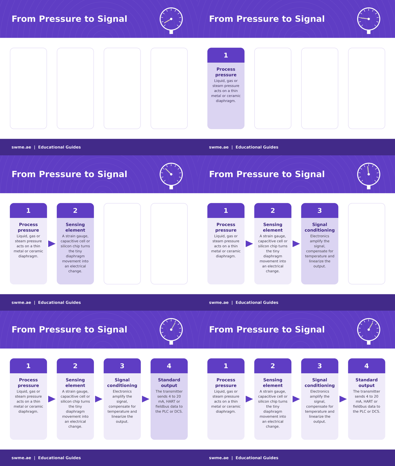
With its sealed sensor and its compensated electronics, a modern transmitter stays stable over years of operation. Many models also include diagnostics that warn you when the sensor or the loop develops a fault.
Did you know?
The 4 to 20 mA standard starts at 4 mA instead of 0 mA for a reason. This live zero lets the system tell the difference between a true zero reading and a broken cable. It also gives the transmitter enough current to power its own electronics. You can convert any current value to engineering units with this 4 to 20 mA scaling calculator.
Pressure Transmitter Sensor Technologies
The sensor is the heart of the instrument. Each technology has strengths that suit different processes. You can read more background on the principles of pressure measurement.
| Sensor type | Principle | Strengths | Typical use |
|---|---|---|---|
| Piezoresistive silicon | Resistance changes with strain on a silicon chip | High sensitivity, compact | General process, hydraulics |
| Capacitive | Diaphragm movement changes capacitance | Very high accuracy, low ranges | Differential pressure, flow and level |
| Thin film | Strain gauge deposited on a stainless steel diaphragm | Rugged, resistant to shock and vibration | Mobile equipment, compressors |
| Ceramic | Thick film or capacitive cell on a ceramic diaphragm | Corrosion and abrasion resistance | Water, wastewater, chemicals |
Gauge, Absolute and Differential Pressure
Before you choose a pressure transmitter, decide which pressure reference your process needs.
To convert between references, use this absolute to gauge pressure calculator. For differential measurement, SWME supplies dedicated differential pressure transmitters designed for high static pressure and stable zero.
Output Signals and Communication
The 4 to 20 mA current loop remains the industry standard. It resists electrical noise over long cable runs, and a reading of 0 mA immediately shows a broken wire.
| Signal | Type | Main benefit |
|---|---|---|
| 4 to 20 mA | Analog | Simple, robust, universal |
| 4 to 20 mA with HART | Analog plus digital | Remote configuration and diagnostics on the same wires |
| Foundation Fieldbus, PROFIBUS PA | Fully digital | Many devices on one cable, rich data |
| 0 to 10 V, Modbus RTU | Voltage or serial | Machinery and building automation |
The HART protocol lets a technician change the range, read diagnostics and check the sensor without opening the loop. This saves time during commissioning and maintenance.
How to Select a Pressure Transmitter
A careful selection prevents most field problems. Work through these points for every pressure transmitter you specify.
- Pressure type and range. Choose gauge, absolute or differential. Select a range where normal pressure sits in the middle third of the span.
- Overpressure limit. Check that pressure spikes and water hammer stay below the rated overload.
- Process temperature. For hot, viscous or crystallizing media, use diaphragm seals with a capillary or cooling element.
- Wetted materials. Match the diaphragm and connection to the medium, for example 316L, Hastelloy, Monel or ceramic.
- Accuracy and stability. Consider total probable error, including temperature effect and long term drift, not only reference accuracy.
- Output and protocol. Confirm what your control system expects, such as 4 to 20 mA with HART.
- Hazardous area approval. In classified zones, specify IECEx or ATEX certification with the correct protection method.
- Connections and enclosure. Select the process connection, cable entry and IP rating to suit the site.
For more detail on classified areas, read our guide on pressure measurement in hazardous areas. If you are comparing compact sensors, our article on 3100 vs 3200 pressure sensors explains the differences.
Pressure Transmitter Installation Best Practice
Liquid service
- Mount the transmitter below the tapping point.
- Trapped gas then rises back into the process.
- Fill impulse lines completely before start up.
Gas service
- Mount the transmitter above the tapping point.
- Condensate then drains back into the process.
- Slope impulse lines continuously toward the tap.
Use a valve manifold so you can isolate, vent and check zero without removing the instrument. SWME supplies manifolds and fittings for single and differential transmitters. In addition, keep impulse lines short and protect them from freezing or overheating.
Finally, verify every transmitter regularly against a reference. Our test and calibration equipment range supports field checks without returning the instrument to a workshop.
Common Mistakes to Avoid
Frequently Asked Questions
What is the difference between a pressure transmitter and a pressure transducer?
A transducer converts pressure into a raw electrical signal, often in millivolts. A transmitter adds electronics that condition this signal into a standard output such as 4 to 20 mA.
How often should a pressure transmitter be calibrated?
Most plants check critical transmitters every 12 to 24 months. Safety loops often need shorter intervals, as defined by your site procedures.
Can a pressure transmitter measure level?
Yes. It can calculate liquid level from hydrostatic pressure when the density is known. See this guide to DP transmitter level measurement.
