Key takeaways
- A vortex flow meter counts the vortices shed by a bluff body placed across the pipe.
- Shedding frequency is proportional to flow velocity, so the meter reads volumetric flow.
- It suits steam, gases and clean, low viscosity liquids, with no moving parts.
- It needs turbulent flow, a minimum velocity and enough straight pipe upstream and downstream.
Steam, compressed air, natural gas and water lines often need a robust meter with no moving parts. A vortex flow meter meets that need by using a simple effect of fluid flow: when a fluid passes a blunt obstacle, it sheds a regular train of swirls whose rate depends on velocity.
This guide explains the principle, the limits and the installation points that matter. SWME supplies flow meters and flow transmitters for process plants across the GCC.
In this guide
Vortex Flow Meter Working Principle
A bluff body, also called a shedder bar, spans the pipe. As fluid flows past it, vortices form alternately on each side and travel downstream in a pattern known as the Karman vortex street. As GlobalSpec states, the frequency of the vortices is proportional to the flow velocity. Each vortex creates an alternating pressure on the bar, and a sensor counts these pulses.
The Strouhal Relationship
The link between frequency and velocity is the Strouhal number, St, a dimensionless value found by experiment. According to Instrumentation Tools, the working formula reduces to f = St × V / d, where f is the shedding frequency, V the velocity and d the width of the bluff body face. The ratio d/D, bar width to pipe bore, is typically 0.22 to 0.26.
Because St stays nearly constant over the working range, frequency rises in a straight line with velocity. Volumetric flow is then velocity times the pipe area. The vortex shedding frequency calculator shows the relationship with your own numbers, and the flow meter K factor calculator converts pulses to volume.
| Width ratio w/D | Strouhal number S |
|---|---|
| 0.1 | 0.18 |
| 0.3 | 0.26 |
| 0.5 | 0.44 |
Experimental Strouhal values quoted by GlobalSpec for different bar width ratios.
Main Parts of a Vortex Meter
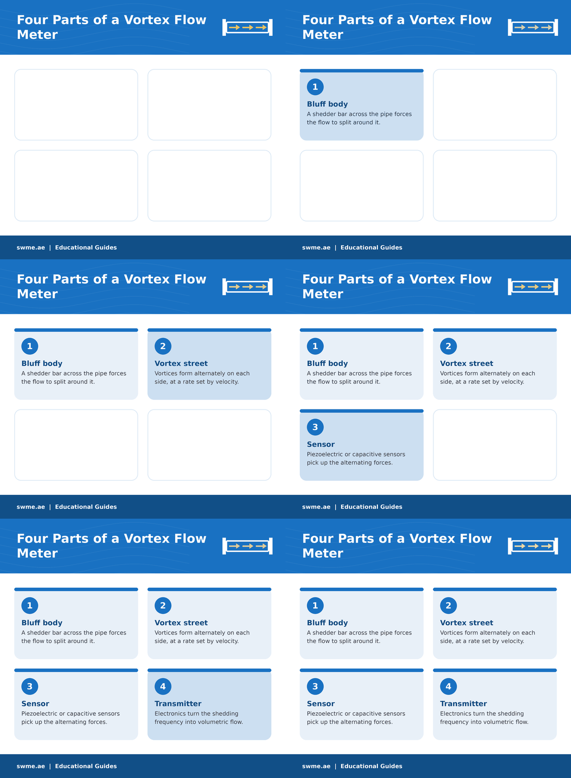
The two common sensor types are a pair of piezoelectric crystals built into the shedder bar, which respond to the alternating shedding forces, and variable capacitance sensors, which respond to tiny movements of the bar. Since the meter has no rotating parts, it needs little maintenance in clean service.
Did you know?
A vortex meter has a natural cut off. Vortices only form reliably above a Reynolds number of about 10,000, so below a certain velocity the meter simply stops counting. You can check your line with the Reynolds number calculator.
Where a Vortex Flow Meter Fits
Good fit
- Steam
- Gases, including natural gas
- Water and low viscosity liquid chemicals
- Lines from 0.5 in up to about 12 in
Poor fit
- High viscosity liquids, which damp the vortices
- Very low flow rates below the cut off
- Heavy solids that wear or clog the bluff body
- Liquids near flashing, where cavitation can occur
For low viscosity liquids such as water, Instrumentation Tools quotes a rangeability of about 20:1 at a maximum velocity of 4.6 m/s. Meters below 0.5 in (12 mm) are impractical, and above 12 in (300 mm) they have limited application. Gas service also needs pressure and temperature compensation because gas is compressible; see the gas flow correction calculator. To compare technologies, read types of flow meters and electromagnetic flow meter working principle.
Installation Tips
- Straight pipe. Provide the straight run upstream and downstream that the manufacturer specifies, away from pumps and valves.
- Size for velocity. Check that the minimum flow stays above the cut off; use the pipe flow velocity calculator.
- Back pressure. Keep enough downstream pressure on liquids to avoid cavitation.
- Clean bar. Erosion or deposits such as wax on the shedder bar change the calibration.
- Noise. Hydraulic noise and loose mounting can disturb the signal.
Common Mistakes to Avoid
If readings drift after installation, our blog on flow meter incorrect readings lists common causes, and Instrumentation Blog has more flow measurement reading.
Frequently Asked Questions
What does a vortex flow meter measure?
It measures volumetric flow by counting the vortices shed by a bluff body, since their frequency is proportional to velocity.
Can a vortex flow meter measure steam?
Yes. Steam, gases and low viscosity liquids are typical applications.
Why does a vortex meter read zero at low flow?
Below a Reynolds number of about 10,000 vortices do not form reliably, so the meter has a low flow cut off.
